

管路布置是船舶详细设计工作的重要组成部分,由于布置空间内设备几何形状复杂,且需考虑避障、敷设成本和安装适用性等要求,设计人员手动布置耗时且容易出错.所以相关学者对自动布置方法开展研究,以提高船舶管路设计工作的质量与效率.通过归纳近些年国内外的相关研究,本文从数学模型和布置算法两个角度进行分析.
然而,上述研究尚存在如下有待解决的问题:① 元启发式和混合式算法的初始化过程需依赖人工经验设置多种优化参数,其求解质量受参数值影响较大;② 不同优化目标所对应的权重系数量级差距较大,在求解不同的船舶管路布置问题时需重新调节,鲁棒性较低;③ 不能根据设计师的不同实际需求获得相应的布置方案.由于Astar算法具有无需参数调节及求解效率高的特点,本文引入分支管路拆分、标记网格以及父子网格的搜索策略扩展了传统Astar算法的目标代价,提出一种网格归一化Astar (grid normalized Astar, GNAstar)的布置方法,并分别采用仿真案例和船舶机舱内不同的管路系统,与传统Astar算法以及考虑同样约束条件和布置目标的蚁群[10]和粒子群-Astar[17]文献算法进行布置结果比较,验证了GNAstar算法的有效性与鲁棒性,设计人员可设置归一化权重系数求解出满足不同设计需求的布置方案,进一步提升船舶管路布置工作的自动化水平和质量.
1 船舶管路布置数学模型
1.1 约束条件
通过对上述相关文献的调研,可将船舶管路布置工作需考虑的主要约束分为以下几类.
(1) 物理约束(physical constraints, P1~P4). P1为管路需连接指定的设备接口;P2为管路与设备之间无干涉;P3为不同管路之间无干涉;P4为管路应沿着舱室空间正交布置.
(2) 安装适用性约束(installation constraints, I1~I3). I1为管路应尽可能沿舱壁和甲板敷设;I2为并行管路应尽可能成束敷设;I3为分支管路应可能沿公共区域敷设.
(3) 经济约束(economic constraints, E1~E3). E1为管路长度应尽可能短;E2为弯头的消耗数量应尽可能少;E3为管路的安装适用性长度(符合 I1~I3约束的管路长度)应尽可能长.
(4) 顺序约束(sequence constraints, S1~S2). S1为优先布置重要设备之间的管路;S2为优先布置尺寸较大的管路.
其中,物理约束主要根据管路的接口坐标位置,从几何角度指出布置算法的路径搜索方向及障碍物坐标;安装适用性约束进一步指明管路的优先搜索区域,使管路的布置路径尽可能适合管路实际工程安装; 经济约束和顺序约束则分别确定出布置算法的目标代价和管路敷设顺序.通过以上分析,这些约束的具体表示形式如下:
包围盒,P2; 分支管路拆分,I3; 标记网格,P3、I1~I3; 归一化权重,E1~E3; 父子网格搜索,P1、P4、S1~S2.
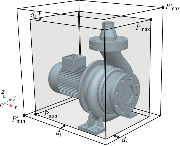
1.2 设备简化
式中:(xmin,ymin,zmin)和(xmax,ymax,zmax)分别为水泵原有的包围盒对角顶点Pmin和Pmax的坐标;dx,dy,dz分别为水泵在3个方向上预留的操作维修距离.
图1
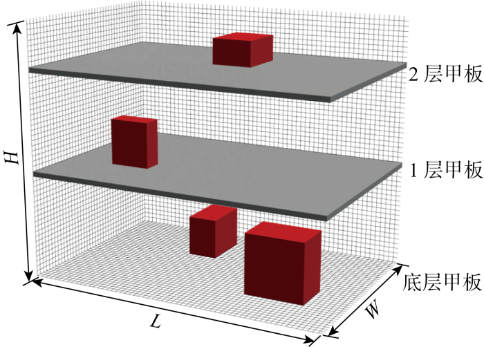
1.3 空间表示
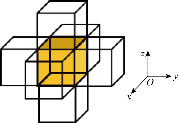
如图2所示,将尺寸为L×W×H的管道布置空间划分为若干三维网格单元,空间内的原始坐标与网格坐标的转换关系如下:
式中:(gx, gy, gz)为三维网格坐标;(xo, yo, zo)为三维原始坐标;Math. floor ()为向下取整函数;g为单元网格尺寸.
图2
为保证布置算法的求解质量与效率,将当前布置问题的最小管路直径作为单元网格尺寸, 其余尺寸管路则通过下式向外延伸对应数量的网格:
式中:E为扩展网格的数量;Math.ceil()为向上取整函数;D为管路直径.
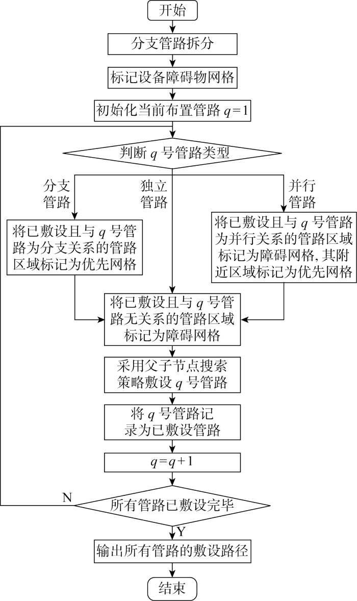
2 GNAstar算法
为实现船舶管路(包括多条独立、并行与分支管路)的综合布置,对GNAstar算法进行设计,整体流程如图3所示.图中:q为当前布置管路编号.
图3
2.1 分支管路拆分
分支管路是一种具有多个接口的管路类型,将其拆分成多条单管路可以使分支管路与其他类型管路同时进行布置求解,具体过程如下.

输入 所有分支节点的网格坐标
N: 分支节点数量
输出 分支管路的共有起点网格坐标
1 for i=1 to N
2 设置 Gi 为空集
3 for j=1 to N
4 if i=j
5 j=j+1
6 else
7 以分支节点i 与j作为边界,将边界内的所有网格坐标添加到Gi集合中
8 j=j+1
9 删除Gi集合中的重复网格坐标
10 %end for
11 比较N个集合
12 选择包含网格坐标数量最多的集合Gk 所对应的分支节点k作为共有起点网格
13 %end for

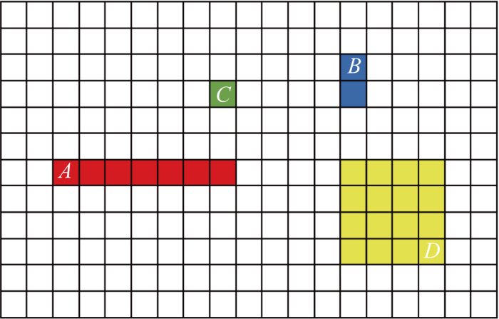
为直观地描述分支管路的拆分过程,以图4所示的4分支管路为例, GA,GB, GC, GD 4个节点集合分别包含7、2、1、16个网格坐标.因此,选择节点D作为该4分支管路的共有起点,并将其拆分为3个具有分支关系的独立管路,分别为D→A、D→B、D→C.
图4
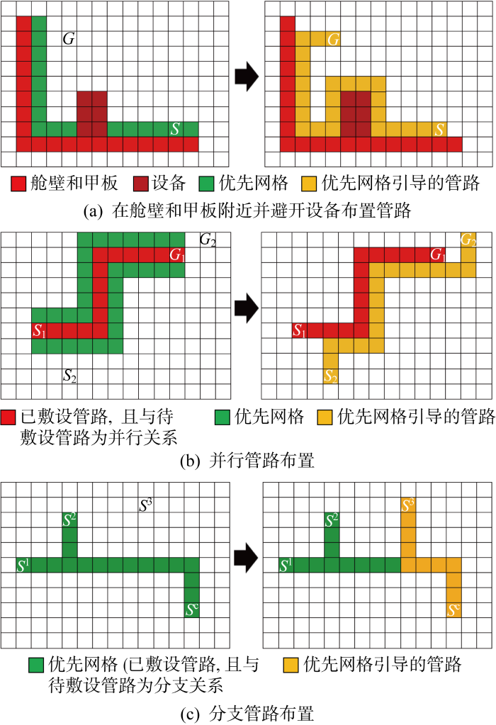
2.2 网格标记
网格标记示意图如图5所示.图中:S为管路起点;G为管路终点;S1和S2分别为2条并行管路的起点;G1和G2分别为2条并行管路的终点;S1, S2和S3分别为分支管路的3个分支点;Sc为分支管路的共有起点.所有网格标记为禁止网格、优先网格和一般网格,分别对应图5中的红色、绿色和白色网格区域.禁止网格主要包括设备、舱壁、甲板以及已敷设且没有分支关系的管路;优先网格主要是有利于管道安装的区域,包括舱壁与甲板附近(见图5(a))、并行管路附近(见图5(b))和分支管路的公共网格(见图5(c));一般网格主要是处上述网格外的可敷设管路区域.在3种网格的引导下,管路即可在满足约束条件的同时向着设计人员所期望的区域搜索布置方案.
图5
2.3 父子网格搜索
Astar是静态网络中搜索最短路径的确定式算法[22],基本思想是从起始点S开始,遍历到S代价最低的相邻网格,直至终点G为止.代价函数定义为
gB(n)=
gI(n)=
h'(n)=abs (xn-xG)+abs (yn-yG)+abs (zn-zG)
w1+w2+w3=1
式中:gB(n), gI(n)分别是弯头消耗与安装适用性长度;n'是网格n的父网格,n″是网格n'的父网格;(xn, yn, zn), (xG, yG, zG) 分别是网格n和终点G的坐标; abs( )是绝对值函数;w1, w2, w3分别是3个子目标的归一化权重.父子网格搜索过程如下.
图6
输入 起点网格S, 终点网格G
输出 搜索的管路结果
1 将起点网格S添加到开放列表O中
2 while O≠⌀
3 在O中找到最小代价f'(n)所对应的网格n
4 从O中删除网格n,并将网格n添加到封闭列表C中
5 if 网格n是终点网格G
6 保存搜索的管路结果
7 % end while
8 else
9 生成网格n的6个子网格,并删除已在封闭列表C中的子网格
10 for 每个子网格ni ∉ C i∈(1, 2, 3, 4, 5, 6)
11 if ni∈O and f'(ni)>g'(ni) + h'(ni)
12 通过式(5)更新f'(ni)
13 else
14 通过式(5)计算f'(ni),将网格ni添加到O中
15 % end for
16 % end while
2.4 目标代价
针对不同管径和不同类型的管路,可通过下式计算出q号管路的长度代价fL,q,弯头消耗数量代价fB, q及安装适用性长度代价fI,q:
式中:Lq,Bq分别表示q号管路的长度与弯头消耗数量;L'q表示q号管路沿舱壁或甲板布置的长度;
3 案例验证
3.1 仿真案例
表1 设备网格坐标
Tab.1
| 设备编号 | x范围 | y范围 | z范围 |
|---|---|---|---|
| I | (20, 29) | (0, 3) | (0, 26) |
| II | (25, 27) | (44, 49) | (0, 8) |
| III | (0, 8) | (10, 15) | (0, 10) |
| IV | (0, 8) | (30, 34) | (0, 10) |
| V | (20, 30) | (20, 30) | (0, 18) |
| VI | (41, 49) | (20, 28) | (0, 20) |
表2 管路接口网格坐标
Tab.2
| 管路编号 | 类型 | 连接设备 | 接口坐标 |
|---|---|---|---|
| 1 | 分支 | I | (24, 2, 26) |
| II | (26, 46, 8) | ||
| III | (2, 12, 10) | ||
| IV | (5, 32, 10) | ||
| 2 | 并行 | III | (6, 12, 10) |
| VI | (45, 23, 20) | ||
| 3 | 并行 | IV | (6, 32, 10) |
| VI | (45, 25, 20) | ||
| 4 | 独立 | I | (29, 1, 20) |
| VI | (45, 20, 16) |
图7
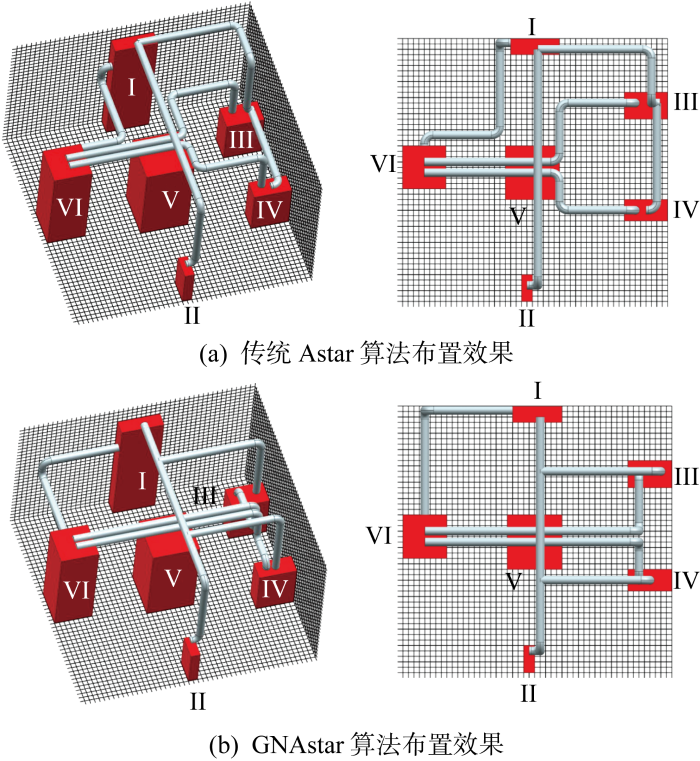
表3 仿真案例计算结果
Tab.3
| q | L/B/I | |
|---|---|---|
| 传统Astar算法 | GNAstar算法 | |
| 1 | 135/6/0 | 137/6/30 |
| 2 | 60/3/25 | 60/3/49 |
| 3 | 56/3/25 | 56/3/49 |
| 4 | 39/4/0 | 39/2/20 |
| 总计 | 289/16/50 | 291/14/148 |
3.2 船舶机舱管路案例
为进一步验证GNAstar算法的有效性,以比例缩小的船舶机舱内(布置空间为 2 000 mm×4 000 mm×3 500 mm)脱硫和燃油管路系统为例,与考虑同样约束条件和优化目标的蚁群[10]、粒子群-Astar[17]文献算法进行布置效果比较.机舱内设备的整体分布情况如图8所示,管路类型、编号顺序、管径和所连设备等布置信息如表4所示,每种方法对于两种机舱管路系统的计算结果如表5所示.在实际的船舶管路布置工作中,设计师有时会根据任务需要,重点关注管路在优先区域的布置情况.因此除了考虑一般的布置工况外(w1=0.3, w2=0.3, w3=0.4,GNAstar-I),还对此类特殊需求的布置工况进行测试(w1=0.1, w2=0.2, w3=0.7,GNAstar-II), 两种工况下GNAstar算法所求解的管路布置效果分别如图9和10所示.
图8
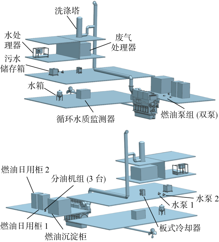
表4 机舱管路布置信息
Tab.4
| 管道系统 | q | 类型 | 连接设备 | 坐标/mm | 直径/mm |
|---|---|---|---|---|---|
| 脱硫系统 | 1 | 分支 | 循环水质监测器洗涤塔 | (580, 3 220, 2 320) | 300 |
| (610, 3 400, 3 180) | |||||
| (610, 3 400, 3 130) | |||||
| (610, 3 400, 3 080) | |||||
| 2 | 并行 | 水处理器 | (170, 3 420, 2 770) | 220 | |
| 污水储存箱 | (220, 3 355, 2 600) | ||||
| 3 | 并行 | 水处理器 | (170, 3 460, 2 770) | 220 | |
| 废气处理器 | (480, 3 300, 2 770) | ||||
| 4 | 分支 | 废气处理器 | (360, 3 570, 2 800) | 100 | |
| 水泵1 | (440, 3 548, 2 557) | ||||
| 水泵2 | (440, 3 448, 2 557) | ||||
| 5 | 分支 | 板式冷却器 | (603, 3 297, 2 537) | 100 | |
| 水泵1 | (448, 3 448, 2 537) | ||||
| 水泵2 | (448, 3 548, 2 537) | ||||
| 6 | 并行 | 板式冷却器 | (620, 3 297, 2 587) | 100 | |
| 循环水质监测器 | (670, 3 220, 2 320) | ||||
| 7 | 并行 | 板式冷却器 | (600, 3 297, 2 587) | 100 | |
| 水箱 | (245, 3 240, 2 300) | ||||
| 8 | 独立 | 洗涤塔 | (650, 3 400, 2 980) | 100 | |
| 板式冷却器 | (620, 3 297, 2 537) | ||||
| 燃油系统 | 1 | 分支 | 主机 | (1 030, 2 200, 2 320) | 600 |
| 燃油泵1 | (1 170, 2 270, 2 330) | ||||
| 燃油泵2 | (1 170, 2 130, 2 330) | ||||
| 2 | 独立 | 燃油日用柜1 | (1 330, 2 270, 2 330) | 600 | |
| 燃油泵1 | (1 210, 2 270, 2 330) | ||||
| 3 | 独立 | 燃油日用柜2 | (1 330, 2 130, 2 330) | 600 | |
| 燃油泵2 | (1 210, 2 130, 2 330) | ||||
| 4 | 分支 | 分油机1 | (1 385, 2 430, 2 320) | 480 | |
| 分油机2 | (1 410, 2 430, 2 320) | ||||
| 燃油沉淀柜 | (1 400, 2 530, 2 330) | ||||
| 5 | 并行 | 燃油沉淀柜 | (1 400, 2 530, 2 330) | 480 | |
| 分油机3 | (1 475, 2 430, 2 320) | ||||
| 6 | 分支 | 分油机1 | (1 370, 2 390, 2 320) | 480 | |
| 分油机2 | (1 430, 2 390, 2 320) | ||||
| 燃油日用柜1 | (1 460, 2 265, 2 330) | ||||
| 7 | 并行 | 燃油日用柜2 | (1 460, 2 130, 2 330) | 480 | |
| 分油机3 | (1 490, 2 390, 2 320) |
表5 机舱管路计算结果
Tab.5
| 管路系统 | q | L/B/I | |||
|---|---|---|---|---|---|
| 蚁群 | 粒子群-Astar | GNAstar-I | GNAstar-II | ||
| 脱硫系统 | 1 | 1 490/4/860 | 1 130/3/1 040 | 1 130/3/1 040 | 1 190/5/1 100 |
| 2 | 278/4/101 | 278/4/176 | 278/4/101 | 278/4/176 | |
| 3 | 470/2/0 | 500/4/455 | 500/3/180 | 500/5/460 | |
| 4 | 494/2/0 | 494/2/0 | 494/4/67 | 494/4/67 | |
| 5 | 700/3/356 | 700/3/356 | 700/3/356 | 700/3/356 | |
| 6 | 638/4/364 | 638/3/134 | 616/3/443 | 698/5/546 | |
| 7 | 432/4/329 | 432/4/316 | 445/4/345 | 445/4/345 | |
| 8 | 464/4/434 | 464/4/434 | 464/4/434 | 486/4/462 | |
| 总计 | 4 966/27/2 444 | 4 636/27/2 911 | 4 627/28/2 966 | 4 791/34/3 512 | |
| 燃油系统 | 1 | 286/4/117 | 276/4/158 | 276/4/158 | 294/6/234 |
| 2 | 120/0/0 | 120/0/0 | 148/4/100 | 148/4/100 | |
| 3 | 120/0/0 | 120/0/0 | 148/4/100 | 148/4/100 | |
| 4 | 200/4/85 | 173/4/150 | 173/4/150 | 190/6/150 | |
| 5 | 310/4/85 | 310/4/85 | 310/4/270 | 310/4/270 | |
| 6 | 321/3/117 | 321/4/117 | 298/5/270 | 333/5/272 | |
| 7 | 190/4/85 | 190/4/75 | 202/5/164 | 202/5/164 | |
| 总计 | 1 547/19/489 | 1 510/20/585 | 1 555/30/1 212 | 1 625/34/1 290 | |
图9
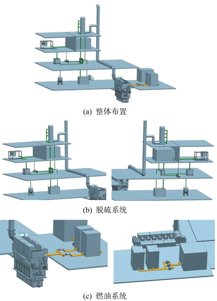
图10
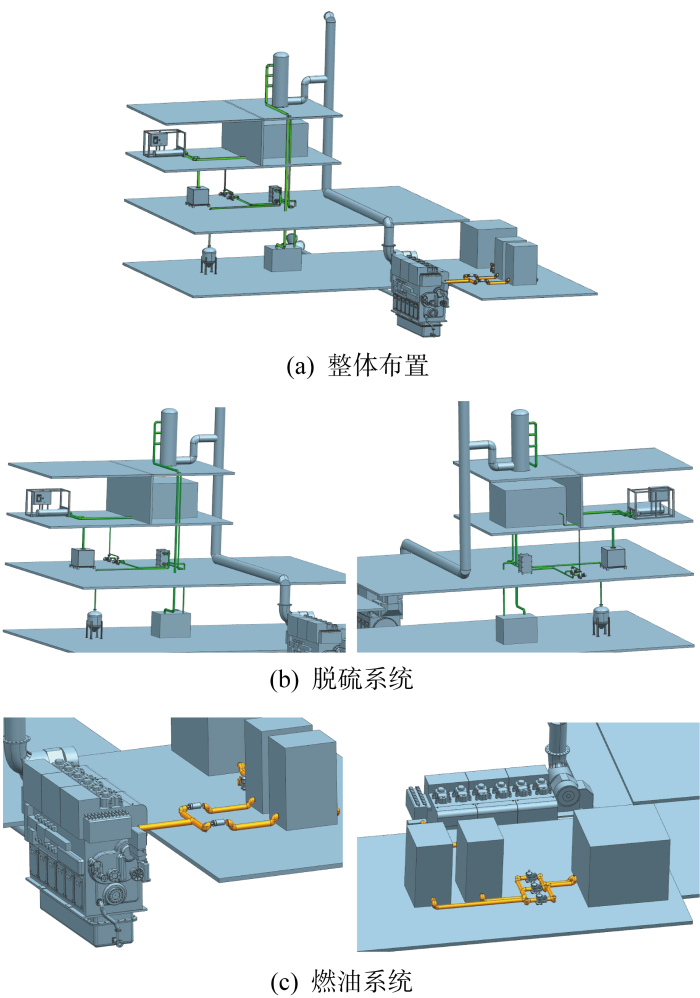
通过比较不同算法的计算结果可知:蚁群与粒子群-Astar算法所求解两种管路系统中的弯头消耗数量均少于GNAstar算法,但两种算法均存在管路安装适用性低的问题(如脱硫系统的4号管路,燃油系统的2号和3号管路,其安装适用性长度均为0),不符合经济性要求,并且受其启发式参数和权重系数量级差距较大的影响,虽然所求解的燃油管路总长度略低于GNAstar算法,但脱硫管路的总长度较高,在求解不同的管路布置问题时需要调节有关参数和权重系数,鲁棒性较低;而GNAstar算法虽然在管路总长度和弯头消耗数量略高于前两种文献算法, 但两种管路系统中的每条管路均支持实际工程安装,满足经济性要求且鲁棒性较好.此外,GNAstar-I与GNAstar-II 两种布置结果与初始设定的权重目标比例均保持一致,相比于GNAstar-I,GNAstar-II 的布置方案虽然在管路总长度和弯头消耗数量方面略高,但可安装长度所占管路总长度的比例更高(如脱硫系统的1号、2号和3号管路,以及燃油系统的1号管路),设计师可根据实际需求便捷地调节GNAstar算法中不同目标的归一化权重系数,从而获得相应的布置方案.
4 结论
针对目前船舶管路布置方法中存在的依靠人工经验调节算法参数,权重系数的设置量级差距较大,以及无法根据实际需要获得不同布置方案的问题,本文在考虑多种实际约束的条件下通过包围盒和网格法建立数学模型,在此基础上对传统Astar算法进行改进,提出了一种船舶管路布置的GNAstar算法:
(1) 通过分支管路拆分、网格标记和父子网格搜索策略,将传统Astar算法仅考虑长度的目标扩展成包括长度、弯头消耗和安装适用性在内的管路综合设计目标,从而实现了不同目标所对应权重系数的归一化,不仅无需人工调节算法参数,且可同时求解包含分支、并行和独立管路在内的混合管路布置问题.
(2) 结合混合管路布置的仿真案例,将传统Astar算法与GNAstar算法进行对比,结果表明GNAstar算法可使管路尽可能沿分支管路公共部分、有利于并行管路成束以及舱壁等优先区域进行布置,所求解方案的经济性明显优于传统Astar算法.
(3) 以船舶机舱内脱硫与燃油管路系统为例,通过与文献中的蚁群和粒子群-Astar算法进行比较,验证了GNAstar算法可保证每条管路均符合经济性要求,鲁棒性较好,且设计人员可通过设置不同目标的归一化权重系数来获得相应的布置方案,为进一步提升船舶管路布置工作的自动化水平和质量提供了参考.
参考文献
The development of a practical pipe auto-routing system in a shipbuilding CAD environment using network optimization
[J].
A discrete hybrid algorithm based on Differential Evolution and Cuckoo Search for optimizing the layout of ship pipe route
[J].
Auto-routing methods for complex ship pipe route design
[J].
Ship pipe routing method based on genetic algorithm and cooperative coevolution
[J].
基于改进遗传算法的船舶管路布局设计
[J].
DOI:10.3778/j.issn.1002-8331.1906-0251
[本文引用: 1]

针对船舶管路布局设计中的路径规划问题提出一种改进型遗传算法求解方法。建立船舶管路布局设计问题的模型空间、约束条件和优化目标;提出一种基于连接点网格的定长编码方法,结合该编码方法设计了适合改进遗传算法应用的适应度函数和交叉、变异算子,定长编码可降低遗传算子设计复杂度和非法个体修补代价;提出在进化流程中嵌入以“去折弯”和“改模式”两种改善型变异方法构建的爬山操作,以提升算法收敛性和寻优能力。通过仿真实验验证所提算法具有可行性和先进性。
Ship pipe route design based on improved genetic algorithm
[J].
DOI:10.3778/j.issn.1002-8331.1906-0251
[本文引用: 1]
<p>In order to solve the Ship Pipe Route Design(SPRD) problem, an improved Genetic Algorithm(GA) optimization method is proposed. Firstly, the model space, constraint conditions and optimization objectives are established for the SPRD problem. Then a fixed-length encoding method based on connection-grids is proposed. Combined with this method, the fitness function and genetic operators such as crossover and mutation are designed for the improved GA. The fixed-length encoding simplifies the implementation of the genetic operators, and can reduce the cost of illegal individual repair. In addition, two improved mutation methods, i.e., “bend-remove” and “mode-change”, are embedded in the evolutionary process as the hill-climbing operator to improve the convergence and optimization abilities of the algorithm. Finally, a simulation experiment is conducted to verify the feasibility and advancement of the proposed algorithm.</p>
Branch-pipe-routing approach for ships using improved genetic algorithm
[J].
DOI:10.1007/s11465-016-0384-z
[本文引用: 1]
Branch-pipe routing plays fundamental and critical roles in ship-pipe design. The branch-pipe-routing problem is a complex combinatorial optimization problem and is thus difficult to solve when depending only on human experts. A modified genetic-algorithm-based approach is proposed in this paper to solve this problem. The simplified layout space is first divided into three-dimensional (3D) grids to build its mathematical model. Branch pipes in layout space are regarded as a combination of several two-point pipes, and the pipe route between two connection points is generated using an improved maze algorithm. The coding of branch pipes is then defined, and the genetic operators are devised, especially the complete crossover strategy that greatly accelerates the convergence speed. Finally, simulation tests demonstrate the performance of proposed method.
船舶管路智能布局优化设计
[J].
Intelligent layout optimization design of ship pipe
[J].
A particle swarm optimization based approach for ship pipe route design
[J].
改进自适应惯性权重粒子群算法及其在核动力管道布置中的应用
[J].
Improved particle swarm algorithm with adaptive inertia weight and its application in nuclear power pipeline layout
[J].
A co-evolutionary improved multi-ant colony optimization for ship multiple and branch pipe route design
[J].
Ship pipe route design using improved multi-objective ant colony optimization
[J].
多蚁群协进化的船舶多管路并行布局优化
[J].
Multi ant colony cooperative coevolution for optimization of ship multi pipe parallel routing
[J].
Improved ant colony optimization algorithm and its application to solve pipe routing design
[J].
A human-computer cooperation improved ant colony optimization for ship pipe route design
[J].
舰船管路布置 PG-MACO 优化方法
[J].
DOI:10.16183/j.cnki.jsjtu.2022.508
[本文引用: 1]
针对舰船管路设计效率低下的问题提出一种管路布置优化方法.综合考虑安全性、经济性、协调性和可操作性等工程背景建立优化数学模型,改进蚁群算法在处理混合管路布置工况下的缺陷,提出优化可行解搜索的空间状态转移策略,提升信息素启发效果并加速算法收敛的信息素扩散机制,面向混合管路布置工况设计多蚁群协同进化机制.基于二次开发技术实现本方法在第三方设计软件上的应用,采用核级一回路管道布置工程案例进行验证.结果表明信息素高斯扩散多蚁群优化(PG-MACO)算法的性能和布置效果优于传统蚁群算法,寻路效率提升58.38%,收敛代数缩短43.24%,布置结果中管路长度缩短33.88%,管路折弯次数减少41.67%,验证了本方法的有效性和工程实用性.
PG-MACO optimization method for ship pipeline layout
[J].
An ant colony optimization-genetic algorithm approach for ship pipe route design
[J].
Ship pipe route design using improved A* algorithm and genetic algorithm
[J].
Optimal design of ship branch pipe route by a cooperative co-evolutionary improved particle swarm genetic algorithm
[J].
A pseudo-distance algorithm for collision detection of manipulators using convex-plane-polygons-based representation
[J].
Continuous collision detection for two moving elliptic disks
[J].
Correction to ‘A formal basis for the heuristic determination of minimum cost paths’
[J].
3D facility layout problem
[J].
基于无障碍凸区域的无人机在线航迹规划
[J].
Online trajectory planning of UAV based on convex obstacle-free area
[J].
DOI:10.12341/jssms20355
[本文引用: 1]
A method based on obstacle-free convex area is proposed to solve the problem of UAV (Unmanned Aerial Vehicle) online trajectory planning. Firstly, A* algorithm based on probabilistic roadmap (PRM) is used to plan a global path off-line. Then, the path planned above is used for local planning by IRIS-Astar algorithm proposed in this paper. The large convex obstacle-free area of the current position is calculated by IRIS (Iterative Regional Inflation By Semidefinite Programming) algorithm, which is used to find a global path point farthest from the current track point to be taken as the local target point. As the UAV travels towards the local target point, the large convex area of the current position is calculated in real time, at the same time, whether the local target point is in this area is judged. If it is, continue to travel towards the local target point; otherwise, the local target point is recalculated. Experimental results show that compared with traditional algorithms, the proposed method can effectively solve the collision avoidance problem of UAV and greatly reduce the energy consumption of UAV.
