

随着经济的发展与人口的增长,城市化进程对空间与资源的有效利用提出了更高的要求,地下空间的开发逐渐成为城市规划的重要方向.顶管施工技术是继盾构施工技术之后发展起来的一种非开挖隧道施工技术,常用于各种地下管线、通道的建设.目前顶管法隧道的施工环境越来越复杂,顶管施工不可避免地会对周围建(构)筑物产生影响,因此研究顶管施工对诸如地表沉降、隧道变形等周围环境影响具有重要意义.
可见顶管施工引起的环境影响,特别是顶管穿越引起下方隧道隆沉的研究较少.本文以杭州砂质粉土地层中某大直径双线平行电力顶管隧道为研究对象,整理了顶管从上方穿越地铁隧道过程中地表沉降、地铁道面隆沉的实测数据,详尽分析了地表横向沉降分布、地表沉降随时间的发展、下方地铁隧道隆沉发展变化的规律.
1 工程概况
1.1 场地环境及工程地质条件
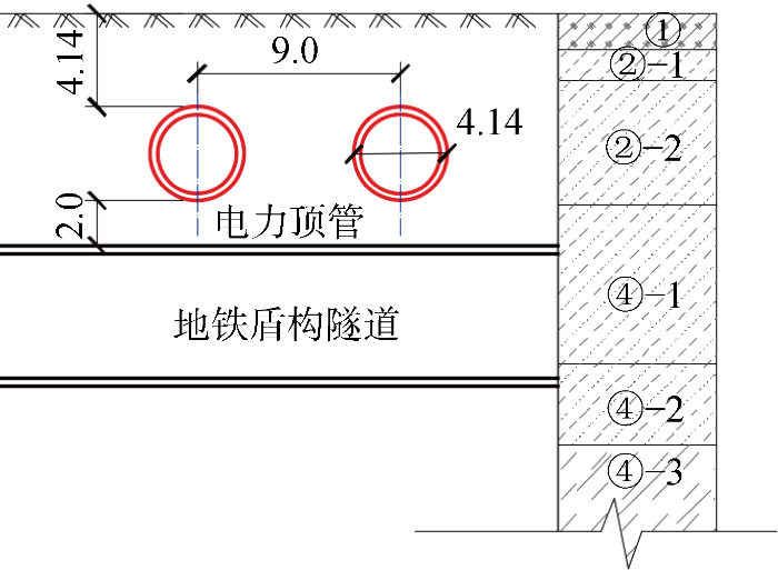
案例为城市高压线路上改下工程,里程总长度2 044.4 m,双线顶管长约285 m,埋深约4.14 m,管节内径3 500 mm,外径4 140 mm,壁厚320 mm,单节长度2.5 m,采用泥水平衡顶管机施工.顶管从北至南由8号井推至9号井,西线顶管先行施工.
图1
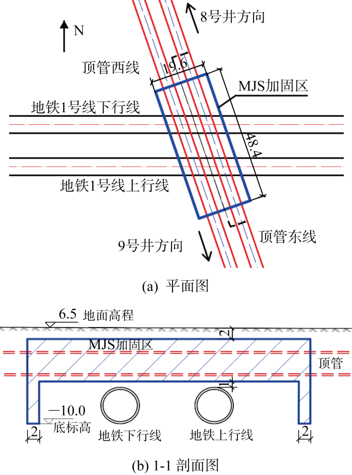
图1
顶管上跨地铁盾构隧道与MJS工法桩加固区的平面图和剖面图(m)
Fig.1
Plan view and sectional view of pipe jacking crossing over subway shield tunnel and reinforcement area of MJS method (m)
表1 土层物理力学参数
Tab.1
| 地层编号 | 地层名称 | h/m | w/% | a1-2/ MPa-1 | ES1-2/MPa | 直剪固快 | kh×104/ (cm·s-1) | kv×104/ (cm·s-1) | |
|---|---|---|---|---|---|---|---|---|---|
| c/kPa | φ/(°) | ||||||||
| ②-1 | 黏质粉土 | 1.6 | 28.1 | 0.21 | 8.75 | 9.1 | 27.8 | 3.1 | 2.7 |
| ②-2 | 砂质粉土 | 3.0 | 26.5 | 0.17 | 10.38 | 7.5 | 28.8 | 5.2 | 4.9 |
| ④-1 | 砂质粉土 | 8.2 | 26.1 | 0.16 | 10.88 | 8.0 | 29.4 | 4.4 | 3.6 |
| ④-2 | 砂质粉土 | 14.0 | 26.0 | 0.17 | 10.64 | 8.7 | 27.7 | 6.5 | 5.8 |
| ④-3 | 粉土夹黏性土 | 18.6 | 28.6 | 0.21 | 9.53 | 10.9 | 26.5 | 2.8 | 1.8 |
| ④-5 | 粉质黏土夹粉土 | 24.5 | 34.5 | 0.43 | 4.60 | 24.6 | 14.3 | — | — |
| ⑤-1 | 淤泥质黏土 | 33.8 | 44.2 | 0.74 | 3.24 | 11.7 | 9.5 | — | — |
图2
1.2 监测点位布设
图3
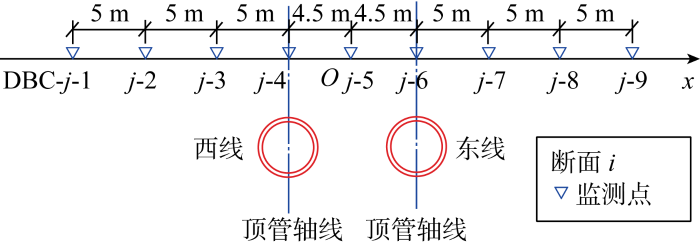
图4
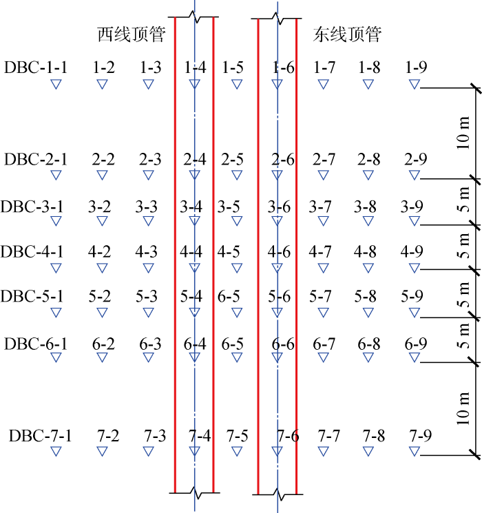
图5
2 顶管施工实测结果分析
2.1 地表横向沉降规律
图6
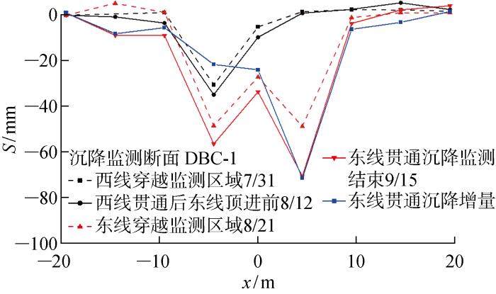
图6
监测断面DBC-1各施工阶段地表沉降
Fig.6
Surface settlement of monitoring section DBC-1 in each construction stage
以图6所示断面DBC-1为例进行分析,西线顶管穿过地表监测区域后,地表沉降槽发展为明显的“V”形,最大沉降量发生在西线顶管轴线上方地表处,占该处最终沉降量的52.7%.西线贯通后,沉降槽保持“V”形,变形基本稳定,轴线上方地面沉降值相对穿越DBC-1断面时仅有少量增长,增量占最终沉降量的9%.当东线顶管贯通后,地表沉降槽由“V”形变为不对称的“W”形,后行顶管轴线上方沉降大于先行顶管.
顶管施工时需要克服开挖面的土压力、刀盘的切削阻力、顶管机外壳和衬砌与土体之间的摩擦力等阻力,这些力的反作用于周围土体使其经历了挤压、剪切等复杂的应力路径并产生附加荷载.顶管通过后,顶管机与衬砌间的管径差形成建筑间隙,土体向建筑间隙内移动,引起土体松动卸荷.在上述附加荷载与卸荷作用反复扰动下,顶管周围加固土体力学性质降低,文献[15]中采用室内模型试验验证了先行隧道对周围土体扰动的现象.因此在经过先行顶管穿越期间对周围土体的扰动后,后行顶管施工将引起更大的土体损失,造成更大的沉降量.
从图6中还可发现,东线顶管顶进时,除了在自身轴线上方产生较大的沉降增量外,在西线顶管上方也产生了较大的沉降增量.原因有:① 如前文所述,东线顶管施工也对周围土体产生了扰动,造成先行顶管四周土体强度降低;② 后行顶管施工过程中产生的力学效应传递到先行顶管衬砌上,使其产生位移和变形,造成先行顶管周围土体发生应力重分布.因此在东线后行顶管的二次扰动下,西线先行顶管地层损失增大,最终使地表沉降量增加[16].由二次扰动引起的西线顶管上方的沉降增量占最终沉降量的38.3%.由此可见,近距离双线平行顶管的开挖顶进是一个相互影响的过程,既要考虑先行顶管对周围土体的扰动,也要考虑后行顶管对先行顶管的二次扰动.
2.2 地铁盾构隧道竖向位移规律
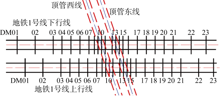
以顶管顶进到影响区域为时间零点,对下方地铁区间的道面累计竖向位移进行统计分析.如图7所示.图中:Stnl为地铁隧道竖向位移,正值表示上浮,负值表示下沉;Ltnl为地铁隧道里程.西线顶管在里程513 m左右处穿越,东线顶管在里程522 m左右处穿越.
图7
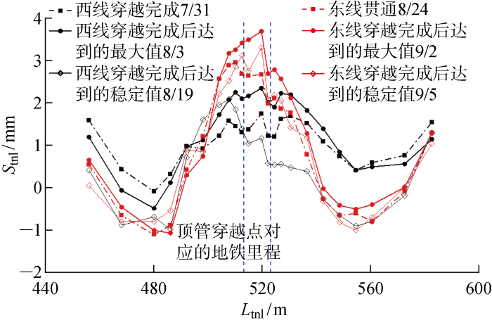
图7
顶管不同施工阶段地铁隧道纵向竖向位移
Fig.7
Settlement of subway tunnel at different construction stages of pipe jacking
当西线顶管穿越完成后(7月31日),如图7中黑色虚线所示,地铁隧道竖向位移曲线表现为“W”形,以两穿越点中线为对称轴呈现较为明显的对称性,竖向位移在数值不大,上浮最大值约为1.70 mm,占最大上浮量的72%;西线穿越完成至西线贯通(8月3日)期间,地铁隧道持续上浮达到最大值2.36 mm,曲线形状基本保持不变,相对于刚穿越完成时,上浮增量为0.66 mm,占最大上浮量的28%.盾构隧道在西线顶管穿越完成后持续上浮直至贯通结束,说明顶管施工过程中管节周围持续的注浆压力等因素对下方盾构隧道上浮有一定影响,造成了上浮的滞后.
东线顶进期间地铁隧道上行线的竖向位移规律与西线顶进期间类似.在东线顶管贯通后(8月24日),曲线峰值对应里程附近隧道继续发生持续上浮,在9月2日达到上浮的最大值,约为3.5 mm.
3 Peck沉降预测公式的适用性
3.1 单线顶管
目前工程界对单线顶管施工由土体损失引起的横向地面沉降计算方法主要采用Peck提出的地面沉降横向分布估算公式[1]:
式中:Smax为隧道轴线上方最大地面沉降;R为隧道半径;i=Kh[2],K为地面沉降槽宽度参数.
图8
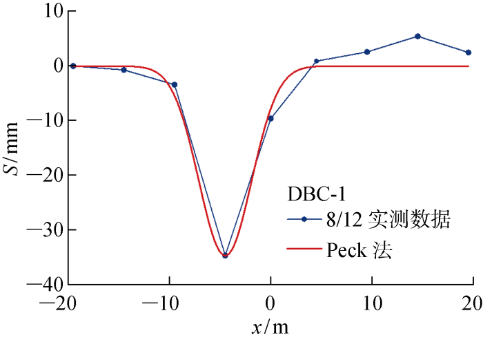
图8
单线顶管断面DBC-1横向地面沉降
Fig.8
Transverse surface settlement of single-line pipe jacking in section DBC-1
表2 单线顶管Peck法横向地面沉降拟合参数
Tab.2
| 断面 | Smax/mm | i/m | K | η/% |
|---|---|---|---|---|
| DBC-1 | 34.78 | 2.60 | 0.63 | 1.65 |
| DBC-2 | 26.89 | 3.17 | 0.77 | 1.56 |
| DBC-3 | 29.64 | 3.40 | 0.82 | 1.84 |
| DBC-4 | 31.53 | 3.35 | 0.81 | 1.93 |
| DBC-5 | 18.14 | 3.71 | 0.90 | 1.23 |
| DBC-6 | — | — | — | — |
| DBC-7 | 19.2 | 3.47 | 0.84 | 1.22 |
| 平均 | 26.7 | 3.28 | 0.79 | 1.60 |
3.2 双线顶管
对于双线平行隧道的地面横向沉降预测,常采用将两条单线隧道地面沉降横向分布公式叠加的方法[7],并将重点放在先行、后行隧道的沉降槽宽度和土体损失率的选取上.
式中:Smax,1=
图9
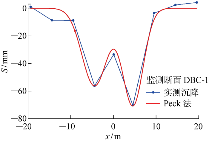
图9
双线顶管断面DBC-1横向地表沉降
Fig.9
Transverse surface settlement of double-line pipe jacking in section DBC-1
表3 双线顶管地表沉降曲线拟合参数
Tab.3
| 断面 | Smax,1/mm | Smax,2/mm | i1/m | i2/m | K1 | K2 | η1/% | η2/% | ηavg/% |
|---|---|---|---|---|---|---|---|---|---|
| DBC-1 | 56.31 | 70.41 | 2.94 | 2.41 | 0.71 | 0.58 | 3.02 | 3.10 | 3.06 |
| DBC-2 | 44.6 | 65.34 | 3.17 | 2.28 | 0.77 | 0.55 | 2.58 | 2.72 | 2.65 |
| DBC-3 | 49.96 | 51.21 | 2.96 | 2.57 | 0.71 | 0.62 | 2.70 | 2.40 | 2.55 |
| DBC-4 | 55.07 | 93.83 | 3.04 | 2.19 | 0.73 | 0.53 | 3.06 | 3.75 | 3.41 |
| DBC-5 | 37.31 | 96.44 | 2.94 | 2.39 | 0.71 | 0.58 | 2.00 | 4.21 | 3.11 |
| DBC-6 | 28.9 | 68.01 | 2.87 | 2.37 | 0.69 | 0.57 | 1.52 | 2.94 | 2.23 |
| DBC-7 | 29.29 | 47.56 | 3.56 | 2.71 | 0.86 | 0.65 | 1.90 | 2.35 | 2.13 |
| 平均 | 43.06 | 70.4 | 3.07 | 2.42 | 0.74 | 0.58 | 2.41 | 3.11 | 2.76 |
从图9可以发现,式(3)可以较好地预测双线顶管施工引起的地表沉降曲线.案例中的双线平行顶管,先行顶管的沉降槽宽度参数K平均值为0.74,大于后行顶管的0.58,是后行顶管的1.28倍;后行顶管土体损失率平均值为3.11%,是先行顶管的1.29倍.
4 地表沉降的时间效应
4.1 地表沉降时间曲线特征
图10
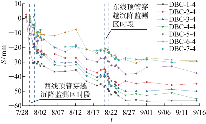
图10
西线顶管上方地表沉降随时间变化
Fig.10
Time-dependent surface settlements above the pipe jacking of the western line
图11
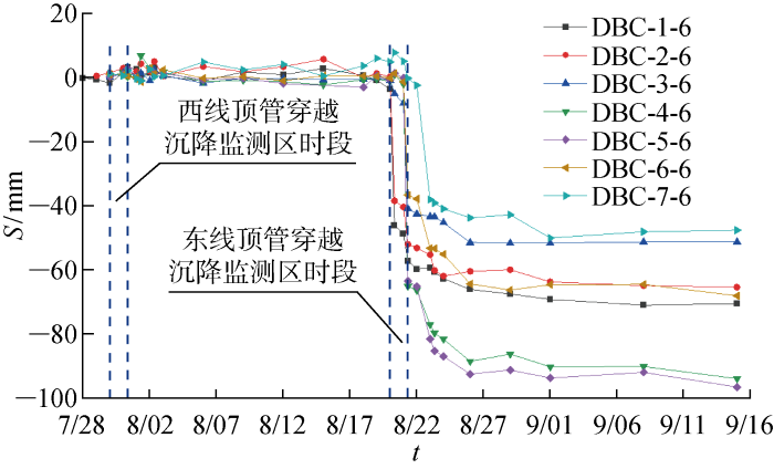
图11
东线顶管轴线上方沉降测点沉降随时间变化
Fig.11
Time-dependent surface settlements above the pipe jacking of the eastern line
由图可见,无论是西线顶管还是东线顶管,在顶管接近沉降监测断面及其后的穿越期间,绝大部分测点观测到较为剧烈的沉降;而在东线顶管接近沉降监测断面及其穿越期间,可以在西线顶管轴线上方各沉降点观测到轻微隆起,且这7个点的隆起特征较为一致,观测到的隆起发生时间主要在穿越开始前一天,此时顶管已顶进66环,推测顶管顶进至接近监测断面时可能发生隆起.
在图10中,可明显发现后行顶管对于先行顶管二次扰动的影响.在先行顶管穿越完成后,先行顶管轴线上方沉降发展若干天后保持稳定甚至有轻微的回弹,但自东线顶管开始顶进以后,先行顶管轴线上方沉降速率明显增大,在穿越完成后的若干天后沉降发展稳定且基本保持不变直至监测结束.
4.2 考虑时间效应的地表沉降预测
式中:Smax(t)为顶管穿越当前断面后轴线上方任意时刻t的地表竖向位移;Smax0为顶管穿越当前监测断面后t0时刻的瞬时竖向位移;α为反映最终竖向位移的参数;β为反映竖向位移发展快慢的无量纲参数.
图12
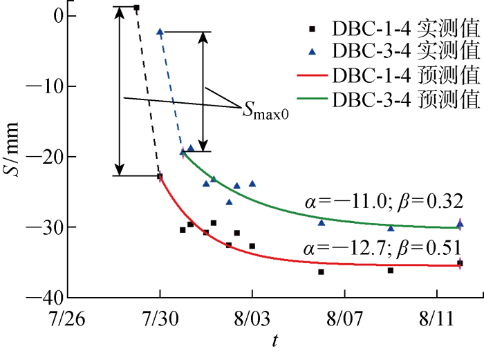
图12
西线顶管上方地面沉降发展预测值与实测值对比
Fig.12
Comparison of predicted and measured values of surface settlement development over pipe-jacking of western line
图13
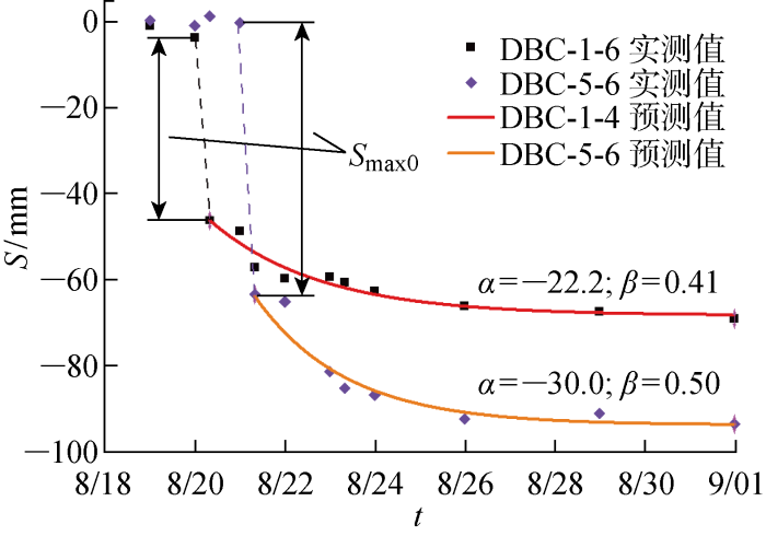
图13
东线顶管上方地面沉降发展预测值与实测值的对比
Fig.13
Comparison of predicted and measured values of surface settlement development over pipe-jacking of eastern line
由于案例所在场地⑤-1淤泥质黏土层埋深33.8 m,距离盾构隧道与顶管较远,所以不考虑该土层对地表沉降的影响.MJS工法以水泥为固化剂对原状土进行加固,通过水泥的水化、凝固作用填充原状土孔隙,改善原状土结构,以提高其强度与抗渗性能.已有研究表明[18],经水泥土加固后,砂质土的渗透系数可以降低两个数量级以上.案例中MJS加固区域如图1所示,可见顶管穿越全程在加固土中进行.由此推测粉砂土地层中顶管施工引起地面沉降呈现时间效应的原因为,顶管顶进前现场采用MJS工法对地铁隧道上方的土体进行了加固,使之形成了具有较高强度和较低渗透性的水泥土,顶管施工产生的超静孔隙水压力消散较慢,在顶管顶进后一段时间内,顶管轴线上方将持续产生沉降后再趋于稳定.
5 结论
通过对杭州砂质粉土地层中大直径双线平行电力顶管上穿已有地铁盾构隧道过程中地表沉降、隧道内道面隆沉的实测数据分析,得到以下主要结论:
(1) 单线顶管横向地表沉降曲线为“V”形,双线顶管横向地表沉降曲线为不对称“W”形,且后行顶管轴线上方沉降大于先行顶管,平行双线顶管施工存在交叉影响.
(2) Peck公式在顶管施工引起的地表沉降曲线预测中适用性较好.本案例对于单线顶管,沉降槽宽度参数K取0.79,土体损失率η取1.6%;对于双线顶管,先行、后行顶管的沉降槽宽度参数K分别取0.74和0.58,前者是后者的1.28倍;先行、后行顶管土体损失率η分别为2.41%和3.11%,后者是前者的1.29倍.
(3) 顶管上跨使地铁隧道产生“W”形沉降曲线,顶管穿越完成后隧道持续上浮至最大值,存在一定的滞后性,顶管贯通暂停施工后隧道产生一定回落.平行顶管上跨施工对下方地铁盾构隧道的影响范围约为4~6倍顶管管径.
(4) 顶管穿越监测断面后产生瞬时地面沉降,且后行顶管的影响大于先行顶管.考虑MJS工法桩加固将降低原状粉砂土的渗透系数,可采用指数函数描述顶管穿越引起地面瞬时沉降后的沉降随时间继续发展规律.
参考文献
Deep excavations and tunneling in soft ground
[C]//
Settlements above tunnels in the United Kingdom-Their magnitude and prediction
[C]//
Volume loss in shallow tunneling
[J].DOI:10.1016/j.tust.2016.06.011 URL [本文引用: 1]
软土地区盾构掘进引起的深层位移场分布规律
[J].
Distribution of deep displacement field during shield tunneling in soft-soil areas
[J].
STANDING J R
Peck公式在我国隧道施工地面变形预测中的适用性分析
[J].
An adaptability study of Peck equation applied to predicting ground settlements induced by tunneling in China
[J].
不同直径盾构隧道地层损失率的对比研究
[J].
Comparative study on ground loss ratio due to shield tunnel with different diameters
[J].
软土双线盾构施工地表变形实测分析与预测
[J].
Prediction and analysis of surface deformation caused by twin shield construction in soft soil
[J].
盾构近距离上穿运营隧道的实测数据分析
[J].
Monitoring data analysis of disturbing effect caused by shield-driven over operating tunnel
[J].
软土地区盾构上穿越既有隧道的离心模拟研究
[J].
Centrifuge modelling of effects of shield tunnels on existing tunnels in soft clay
[J].
顶管施工力学效应的数值模拟分析
[J].
3D numerical analysis on construction mechanics effect of pipe-jacking
[J].
顶管施工中土体损失引起的沉降预测
[J].
Prediction of settlement induced by ground loss during pipe jacking construction
[J].
矩形顶管隧道顶进过程的地层损失
[J].
Stratum loss during pipe jacking of rectangle tunnel
[J].
平行顶管施工引起的地面变形实测分析
[J].
Analysis of site monitoring of ground deformation induced by parallel pipe jacking construction
[J].
多线叠交盾构隧道近接施工模型试验
[J].
Model test on approaching construction of multi-line overlapped shield tunneling
[J].
近间距双线大直径泥水盾构施工相互影响研究
[J].
Study of field monitoring on interaction between twin slurry shield tunnels in close space
[J].
基于分级加载工况的沉降曲线拟合法及工程运用
[J].
Curve fitting method for settlement based on staged loading condition and its engineering application
[J].
