

随着行业发展,注塑生产对制品质量和注塑生产效率均提出了更高要求,而模具温度是一个重要影响因素.在注塑生产过程中,模具的开模时间需要根据零件温度确定,并且不合理的模具温度分布很容易影响熔体的流动与固化,从而导致制品出现留痕、翘曲等问题.通过数值模拟可以预测实验方法很难测试的局部随时间、空间变化的温度场,因而基于注塑成型的周期性研究模具稳态温度场的模拟算法具有重要价值.
现今最常用的模具温度场计算方法为边界元法,Kwon[1]提出将周期变化的模具温度求解视为稳态温度场并采用边界元法求解注塑模具温度的循环平均冷却模型,后续很多学者在该算法的基础上进行了改进与扩展[2-3].然而边界元法只能根据表面网格结点查看型腔部分的温度分布,不能看到模具内的温度场,具有一定局限性,因此相关研究[3⇓-5]采用其他算法对模具的稳态或瞬态温度场进行计算.例如Lin等[4]没有采用传统方法对模具与熔体解耦,而是通过将模具与熔体耦合分析系统瞬态温度场,根据两侧热流相等的约束计算模具-熔体界面传热,并分别利用有限体积法(FVM)和有限单元法(FEM)证明了模拟计算具有可实现性.相对FEM,FVM具有全局守恒和局部守恒的优点,计算形式更加灵活,故本文采用FVM对注塑模具的稳态温度场进行全域计算.注塑模与零件界面常通过对瞬态传热取时间平均的方式计算稳态传热[1],而对于FVM的非结构网格,由于其没有基函数,各单元的物理量值是离散的,所以界面梯度需要通过二阶或高阶插值近似得到[6].另外,一些关于接触界面热量传递方面的研究,如Yang等[7]和Prajapati 等[8]分别对注塑型腔面传热以及增材制造的层间接触热阻进行实验测量并总结了相关特性;Sardo等[9]基于FEM计算模型对界面热机械性能进行平滑处理并使用了各向异性网格加密技术;Ahmmed[10]基于FVM对接触热阻及接触面传热现象进行数值研究,基于分区共轭传热(CHT)方法开发了数值计算模型.然而,上述分界面传热模型对于控制体积各面热流的计算均相互独立,不能满足模型等效为稳态温度场时控制体积的能量守恒特性.针对该问题,本文根据热量守恒特性提出一种改进的型腔边界稳态热流计算方法,基于FVM分别构造了改进前后的节点中心型控制体积[11],对注塑生产中实例模型进行计算,并通过与商业软件模拟结果对比验证算法的准确性.
1 模具稳态传热数学模型
1.1 控制方程及边界条件
基于注塑成型连续生产的周期特性将模具的温度视为稳态场,只考虑注塑成型的冷却阶段,并对计算模型作如下假设:模型材料不可压缩,连续均匀,且具有各向同性;熔体的压力为0,各点均无运动;模具与熔体完全贴合,界面无热阻;忽略熔体内部反应,内部无其他热源.模具稳态温度场的热平衡方程计算公式为
式中:Ω为几何全域.
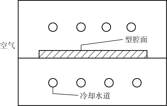
图1为简化的注塑模具示意图,可见模具温度求解域有3个边界条件,分别为空气、型腔面和冷却水道.对各边界计算采用以下数学模型:
式中:Γm为型腔边界;Γe为空气边界;Γc为冷却水道边界;qm为熔体由型腔面传递至模具的平均热流密度;kw为模具的热传导系数;he为空气与模壁之间的换热系数;hc为冷却水与模具之间的换热系数;N为边界面的外法线方向;Te为空气温度;Tc为冷却水的主流温度.
图1
1.2 迭代算法
计算模具温度场时需要将熔体和模具之间的平均热流量作为边界条件,而计算熔体与模具型腔之间的平均热流又需要求解熔体的瞬态温度场,此时注塑模具型腔面温度场为边界条件,因此需要通过迭代实现模具温度场与熔体、模具在模壁上传热的耦合计算.图2为计算注塑模具稳态温度场的流程图,具体说明了注塑模具稳态温度场的计算与迭代过程.图中,n代表第n次迭代,假定模具初始温度场为Tw(0),此时n=0;e为收敛容差.为了提高迭代计算的稳定性,采用低松弛法并引入松弛系数θ.
图2
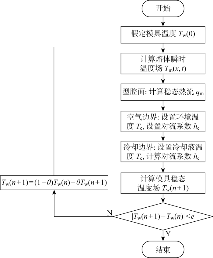
图2
注塑模具稳态温度场模拟流程图
Fig.2
Flow chart of steady-state temperature field simulation of injection mold
2 FVM求解型腔稳态热流
2.1 型腔面传热数学模型
对于塑料熔体瞬态传热,在假设模具温度呈稳态的情况下,将模具型腔面温度场作为边界条件,控制方程如下:
式中:ρm为塑料熔体密度;cm为塑料熔体比热容;km为熔体的热传导系数;ΔTf为控制体积界面处的温度梯度,通过高阶近似[6]求解.容易看出,模具与熔体之间的传热边界条件属于狄利克雷边界条件,经FVM离散可变换为如下形式:
式中:S为控制体积界面的面积矢量;f~nb(C)为控制体积的各边界面,C代指当前控制体积;V为控制体积的体积.ΔTf的求解过程为
式中:Δ
采用节点中心型控制体积,则型腔面上的温度梯度可直接通过节点温度梯度插值得到,熔体边界面上瞬态传热计算公式如下:
将稳态传热等效为瞬态传热的时间平均,得到:
式中:tcycle为注塑周期;I为总时间步;i代表第i个时间步.
2.2 型腔面传热算法改进
将型腔面视为稳态热流边界条件实质上是将注塑周期内熔体温度视作同样的稳态场,因此熔体离散的控制体积体内应满足能量守恒,即控制体积与周围传热量为0.于是在假定模具温度的情况下,熔体部分控制体积上各面热流密度应满足:
式中:qm,j为控制体积第j个面上的稳态热流密度;j为面序号;J为控制体积的面数.
采用上述传统FVM计算稳态型腔面热流时,型腔面所在控制体积各面之间热流量计算相互独立,故综合考虑各面热流,控制体积内热量往往并不守恒,不能满足稳态温度场的特点,在一定程度上影响计算收敛性甚至结果的正确性.基于该问题,利用体积能量守恒特性对型腔面上等效稳态热流算法进行改进,将稳态温度场热量守恒即控制体积各面上热流总和为0作为前提条件,基于控制体积内其他面上的热流计算型腔面上的等效热流,则模具模型边界面上稳态热流通量求解公式可写作以下形式:
式中:qm,b为熔体控制体积型腔边界面上的等效稳态热流通量,假设型腔面在控制体积内序号为J.
图3

图3
型腔面等效稳态热通量改进前后算法对比示意图
Fig.3
Schematic diagram of comparison of algorithms before and after improvement of equivalent steady-state heat flux of cavity surface
3 支架案例数值模拟
图4
经网格划分,型腔面上有 398879 个单元,74877 个节点;模具有 900174 个单元,179301 个节点,模具网格一部分表面与型腔网格的表面重合.支架零件为聚醚醚酮(PEEK)材料,模具为工具钢P-20.采用改进前后FVM算法模拟得到支架模具三维稳态温度场如图5所示.可以看到,改进前后FVM计算得到的模具温度分布相似,由于模具上部与型腔面距离较近,所以温度相对更高,但是改进前后温度场最高值分别为239.7、186.2 ℃,相差近 54 ℃.
图5
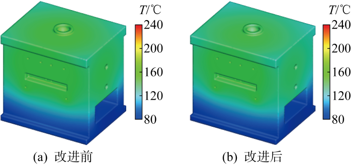
图5
FVM改进前后计算所得支架模具稳态温度场
Fig.5
Calculated steady-state mold temperature of bracket before and after FVM improvement
图6(a)为根据改进后FVM模拟结果提取得到的型腔面温度场,可以看到外边角位置的温度最低约为150 ℃,在肋板与底板相交的T形位置温度最高,约为205 ℃,这是因为T形位置的当量厚度最大,所以冷却速度更慢.但整体上温度分布比较均匀,说明冷却水路的排布较为合理,能够与零件之间均匀传递热量,尽量避免零件产生翘曲等缺陷.
图6
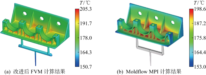
图6
改进后FVM与Moldflow MPI计算所得支架型腔稳态温度场
Fig.6
Steady-temperature field of injection mold cavity of bracket calculated by improved FVM and Moldflow MPI
由于实际注塑模具稳态温度数值模拟的材料模型、边界条件、计算区域较为复杂,难以采用解析解来验证本文算法的正确性.所以要验证数值模拟方法的准确性,首先需要验证根据本文算法所开发的数值模拟程序的正确性.鉴于Moldflow MPI软件在注塑工业领域已广泛应用,假设其在仅考虑指定材料模型、边界条件、计算区域时能得到较为准确的计算结果,即认为其数值模拟程序正确.因此为验证算法的有效性,将比较本文所开发的数值模拟程序与Moldflow MPI在相同材料参数、边界条件下的注塑冷却稳态温度场数值模拟结果的差异.支架为薄壁件,采用双面层单元,通过计算得到Moldflow MPI的型腔面稳态温度场结果如图6(b)所示.将图6(a)与图6(b)对比发现,两者计算结果分布大致相同,Moldflow MPI计算得到的型腔面温度同样呈现出上述温度分布特征,另外根据温度色标可以看出,FVM计算得到的温度数值范围与商业软件的计算结果几乎一致,最大温度值仅相差6.7 ℃.
在注塑成型过程中,模具热量来自于熔体侧的型腔面,模具温度的最大值往往位于型腔面上,所以可以通过对比FVM算法得到的模具温度最大值与Moldflow MPI计算得到的型腔面最大值以比较两者的模拟结果.将改进前后FVM算法与Moldflow MPI计算结果的差值列于表1中.可以看到,经过改进,FVM与Moldflow MPI之间的误差值由 41.1 ℃ 下降到了6.7 ℃.
表1 改进前后FVM模拟支架模型的温度最大值及误差
Tab.1
| 算法 | 温度最大值/℃ | 最大值误差/℃ |
|---|---|---|
| Moldflow MPI | 198.6 | — |
| 传统FVM | 239.7 | 41.1 |
| 改进FVM | 205.3 | 6.7 |
4 托盒支架案例数值模拟
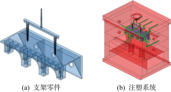
为进一步对改进后的FVM算法进行验证,再次采用改进前后FVM算法对托盒支架零件的注塑模具模型进行模拟计算,托盒支架模型通过一模两件的方式注塑生产,零件如图7(a)所示,浇注系统包括1个主浇道以及2个分流道.支架零件的轮廓尺寸大约为260 mm×45 mm×48 mm,托架的尺寸大约为268 mm×220 mm×53 mm.对包括浇注系统在内的熔体部分进行网格划分,型腔表面被划分为 73664 个单元,36782 个结点.从图中可以看到,支架零件的底下凹陷空间比较狭窄,因此将此处的冷却回路设计成喷流管道.图7(b)为托和支架零件在生产冷却时的系统模型,轮廓尺寸约为 560 mm×600 mm×4570 mm.零件材料为尼龙(PA),模具使用工具钢P-20.
图7
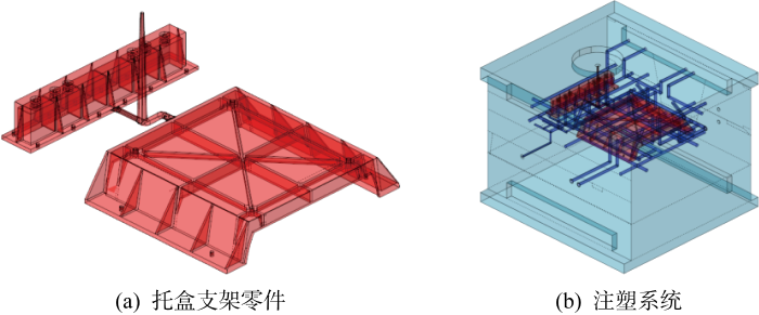
图8
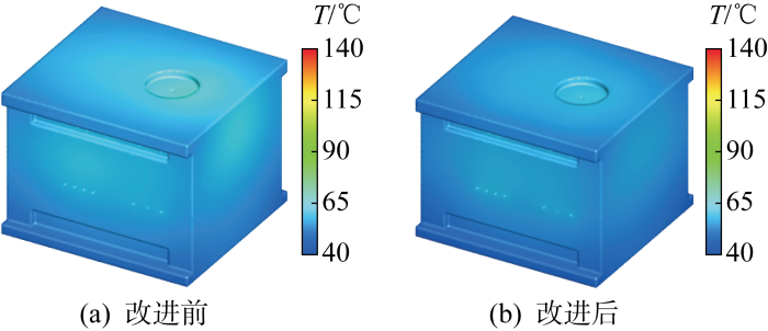
图8
FVM改进前后计算所得托盒支架模型模具稳态温度场
Fig.8
Calculated mold temperature of bracket support before and after FVM improvement
图9为改进后FVM算法与Moldflow MPI计算得到的模具型腔面温度场,图9(a)为FVM算法的计算结果,温度数值分布在61.6~96.7 ℃内;图9(b)为Moldflow MPI计算得到的温度场,数值分布在62.8~110.4 ℃内.对比发现,改进后FVM算法与Moldflow MPI计算的型腔温度场分布情况几乎一致,并且两者温度数值的分布区间绝大部分重叠,这在一定程度上证明改进后FVM算法模拟注塑模具稳态温度场具有较高准确性.为进一步验证改进FVM算法理论的正确性,将改进前后FVM模具温度的最大值以及其与Moldflow MPI型腔温度最大值的比较置于表2中,发现改进前FVM与商业软件最大温度的差值为28.6 ℃,而改进后差值下降至13.7 ℃,证明基于稳态温度场热量守恒特点对型腔边界传热算法改进后,FVM数值模拟解的正确度有了显著提升.
图9

图9
改进后FVM与Moldflow MPI计算所得托盒支架型腔稳态温度场
Fig.9
Steady-temperature field of injection mold cavity of bracket support calculated by improved FVM and Moldflow MPI
表2 改进前后FVM模拟托盒支架的温度最大值及误差
Tab.2
| 算法 | 温度最大值/℃ | 最大值误差/℃ |
|---|---|---|
| Moldflow MPI | 110.4 | — |
| 传统FVM | 139.0 | 28.6 |
| 改进FVM | 96.7 | 13.7 |
然而通过对比改进后FVM与Moldflow MPI计算的温度场结果,容易看出两者数值方面仍存在差异,差异原因主要包括以下几个方面.首先,最主要的差别在于Moldflow MPI无法指定具体模具,而FVM可以自主导入模具.FVM导入的实际注塑模具模型尺寸通常远大于Moldflow MPI默认的模具模型尺寸,因此FVM计算得到的温度结果往往高于Moldflow MPI得到的计算结果.其次,从图6(b)和图9(b)可以发现,Moldflow MPI在模拟计算时没有考虑浇注系统,而实际生产中,注塑浇注系统内充填塑料熔体,因此采用FVM计算熔体温度场时将浇注系统视为型腔的一部分.另外,FVM与Moldflow MPI数值计算方法不同,FVM将几何体离散为三维单元,并对整个模具的几何区域进行模拟,而Moldflow MPI计算时零件被划分为双面流模型的表面网格,仍然采用边界元法计算,通常表面网格的计算精度不如三维网格.综合以上因素,FVM与Moldflow MPI的计算结果数值通常会存在一些差异.
另外,数值模拟最终是否与工业实践结果相一致,除了数值模拟程序本身的正确性之外,还需要考虑工业实践中一些特殊的问题,如精细的材料模型、准确的控制方程、复杂的边界条件等,甚至需要考虑工业实践中的物理化学变化,因此要准确地模拟实际注塑成型过程中稳态温度场,本文数值模拟方法还有待进一步验证和改进.
5 结论
(1) 对基于FVM的注塑模具稳态温度场模拟算法进行探究,针对传统界面梯度法求解模具型腔面等效稳态热流不满足熔体控制体积热量守恒的问题,利用控制体积具有能量守恒的特性改进了等效稳态热流算法.改进算法在求解界面梯度时考虑了型腔面与其所在控制体积其他面之间的关系,将基于节点温度梯度的计算转换为基于控制体积的温度梯度计算.
(2) 分别采用基于传统FVM与改进FVM自主开发了C++数值模拟程序,对支架零件以及托盒支架零件的注塑实例模型进行了模拟,通过将模拟结果与商业软件模拟结果对比验证了依据改进算法所开发的数值模拟程序的正确性;相对传统FVM,改进后FVM的理论结果更加准确,证明了该算法的正确性.同时,本文算法还需要更多算例与注塑实验结果对比以进一步验证和改进.
参考文献
Mold cooling system design using boundary element method
[J].
DOI:10.1115/1.3187898
URL
[本文引用: 2]

Cooling system design in injection molding industries is of great importance because it significantly affects productivity and the quality of the final part. It would thus be very helpful for mold designers to be able to use a computer aided design tool in determining locations of cooling channels and process conditions to achieve uniform cooling and minimum cooling time. Towards this goal, the Boundary Element Method (BEM) has been applied to develop a system of computer aided cooling system design programs: (a) an interactive design program using a two-dimensional BEM and (b) a cooling analysis program using a three-dimensional BEM. In the present work, the injection molding cooling process is simplified by quasi-steady-state heat transfer in terms of cycle-averaged temperature. In this regard, a cycle-averaged heat transfer coefficient between a mold and polymeric material has been introduced for a cycle-averaged boundary condition. In the present paper, discussion centers on the fundamental modeling of the cooling process and the features of the BEM mold cooling design systems.
Transient mold cooling analysis using BEM with the time-dependent fundamental solution
[J].DOI:10.1016/j.icheatmasstransfer.2004.07.006 URL [本文引用: 1]
An acceleration method for the BEM-based cooling simulation of injection molding
[J].DOI:10.1016/j.enganabound.2009.04.001 URL [本文引用: 2]
3D numerical simulation of transient temperature field for lens mold embedded with heaters
[J].DOI:10.1016/j.icheatmasstransfer.2004.10.025 URL [本文引用: 2]
Three-dimensional transient finite element cooling simulation for injection molding tools
[J].DOI:10.1007/s00170-022-09154-8 [本文引用: 1]
Numerical method for coupled fluid flow, heat transfer and stress analysis using unstructured moving meshes with cells of arbitrary topology
[J].DOI:10.1016/0045-7825(95)00800-G URL [本文引用: 2]
Evaluation of the long-term thermal stability of a crushed-rock revetment embankment in pan-Arctic permafrost regions under the effect of snow drift
[J].DOI:10.1016/j.energy.2022.125664 URL [本文引用: 1]
Measurement of anisotropic thermal conductivity and inter-layer thermal contact resistance in polymer fused deposition modeling (FDM)
[J].DOI:10.1016/j.addma.2018.02.019 URL [本文引用: 1]
Simulations of heat transfer in thermoplastic injection molds manufactured by additive techniques
[J].
DOI:10.3139/217.3594
URL
[本文引用: 1]
The cost and quality of complex thermoplastic parts manufactured by injection are traditionally limited by the design constraints on the mold cooling system. A possible way to overcome this problem is to produce the mold by additive manufacturing, which makes it possible to freely design the shape and position of the cooling channels. Such molds can have hollow spaces in order to reduce the manufacturing time by Selective Laser Melting and the use of costly materials. The complex geometry resulting from optimized cooling channels and hollow regions makes the prediction of the cooling system performance difficult. This work aims to devise a numerical methodology for the simulation of heat transfer phenomena between the polymer, the mold and the cooling channels. An Immersed Volume approach is chosen, where the different parts of the domain (i.e. the polymer, the cooling channels, the hollow regions and the mold) are represented implicitly and the thermo-mechanical properties of the materials vary smoothly at the interface between the parts. The energy and momentum equations are solved by a stabilized Finite Element method. In order to accurately resolve the large variations of material properties and the steep temperature gradients at interfaces, state-of-the art anisotropic mesh refinement techniques are employed. In a first step, we perform thermal calculations only. We then consider the proper thermo-mechanical coupling in the packing stage, as well as the ejection stage and the thermal contact resistance between the polymer part and the mold, in order to weight their influence on the part and the mold temperatures. The modeling strategy is first validated on a simple geometry of a center-gated disk and compared with experimental measurements. The agreement between the experimental results and the simulation is good. Simulations are then performed on an industrial case which illustrates the ability of the method to deal with complex geometries.
A finite volume numerical approach for predicting heat transfer in presence of thermal contact resistance
[J].DOI:10.1016/j.tsep.2022.101618 URL [本文引用: 1]
基于改进有限体积法的三维注塑成型充模过程数值模拟
[J].
DOI:10.3901/JME.2015.10.025
[本文引用: 1]
根据界面两侧相邻有限体积流动切应力相等的原则,考虑到相邻有限体积内黏度系数的差异,改进传统有限体积法,并推导改进的有限体积中心速度梯度、界面速度和速度梯度的新的离散格式和计算格式。新的离散格式和计算格式能适用于注塑成型充模过程中型腔内塑料熔体黏度差异较大的情形,避免因黏度的变化导致界面两侧相邻有限体积内塑料熔体流动切应力的急剧变化。同理,根据界面两侧热流量相等的原则,推导有限体积中心温度梯度、界面温度梯度的新的离散格式和计算格式。改进有限体积法能有效提高数值模拟的稳定性和计算精度。采用改进的有限体积法分别模拟圆柱内稳态流动以及盒形件、带凹槽平板、一般三维特征的塑料制品的塑料熔体充模过程,模拟结果与理论精确解、试验结果、商业软件模拟结果吻合。数值算例表明改进的有限体积法能较准确地模拟注塑成型充模过程,也可应用于黏度变化比较大的其他单一流体或多种流体的耦合数值模拟,具有重要的理论和实用价值。
3D simulation of filling stage of plastic injection molding based on improved finite volume method
[J].
DOI:10.3901/JME.2015.10.025
[本文引用: 1]
According to the equal flow shear stress at the interface in adjacent finite volumes, the traditional finite volume method (FVM) is improved in consideration of the viscosity variation in adjacent finite volumes. The new discretization and computing formulae concerning velocity gradient at the center of finite volume, as well as velocity and its gradient at the interface are deduced for the improved FVM. The new discretization and computing formulae are apt to the situation that melt viscosity varies very quickly during the filling stage of plastic injection molding. The improved FVM can avoid steep oscillation of flow shear stress in adjacent finite volume. Similarly, according to equal heat flux at the interface in adjacent finite volumes, the new discretization and computing formulae of temperature gradient are also deduced when the changing of heat conductivity coefficient in adjacent finite volumes is taken into account. Thus the improved FVM results in numerical stability and accuracy in the simulation of filling stage. The presented approach is used to simulate the steady laminar flow in a cylinder and the filling stage of a box, a plate with concave groove and a plastic part with general 3D features. The simulation results agreed well with the theoretic solution, experimental data and those from commercial software respectively. So the improved approach is verified to be able to exactly simulate the filling stage of plastic injection molding. In practice, it can also be theoretically applied in the coupled simulation of other single fluid or multi fluid.
